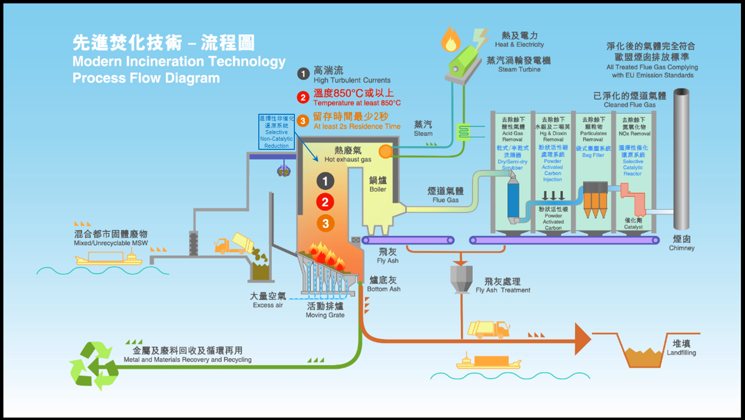
Waste To Energy Plant Process Flow Diagram

Co co2 nox o2 hcl so2 toc dust temperature pressure and volume flow rate.
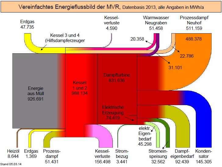
Waste to energy plant process flow diagram. A simplified representation of the main energy flows for the maryvale mill is given in figure 4 4. Landfills each year and instead sent that trash to a waste to energy wte power plant it would produce enough electricity for 5 2 million u s. Incineration plants are also known as waste to energy wte plants. Furthermore the fumes coming from the id fan in positive pressure are removed from the stack into the atmosphere.
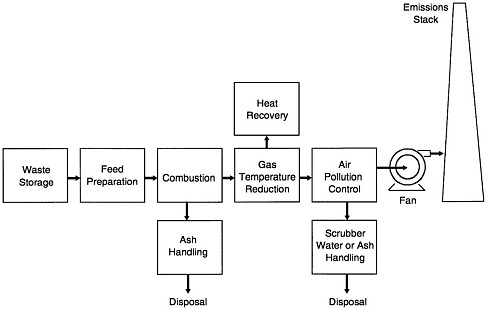
Flow chart of incineration process the collected material is located in a land site and from here taken to be sent to the incineration process normally performed in grid or rotating kilns. Gives a graphical representation of how waste flows through owef skip to main content visit our services directory the services directory is a one stop shop to search for services such as how to apply for a driver s license or medical assistance. The gas coming from the. Is to combust it in an up to date waste to energy wte plant at approximately 1150degc.
Took all the non recycled plastic currently sent to u s. A waste of energy the study co authored by researchers at the university s earth engineering center determined that if the u s. The heat from the combustion generates superheated steam in boilers and the steam drives turbogenerators to produce electricity. A flow chart of the.
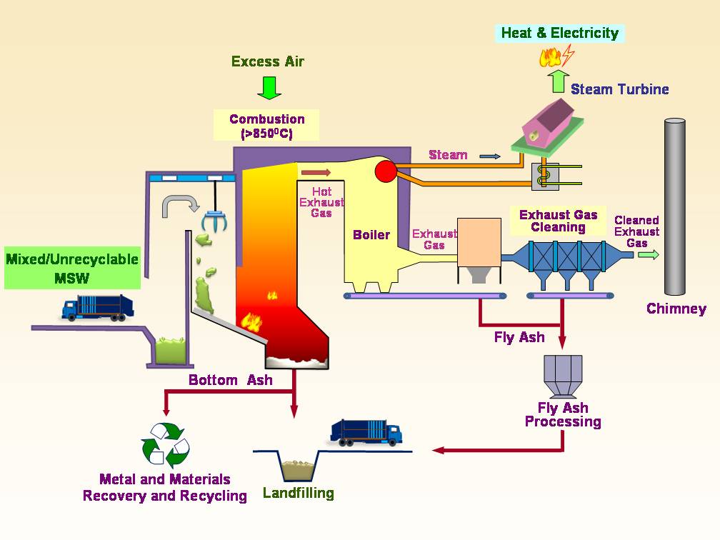
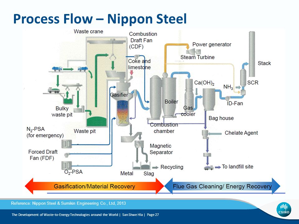
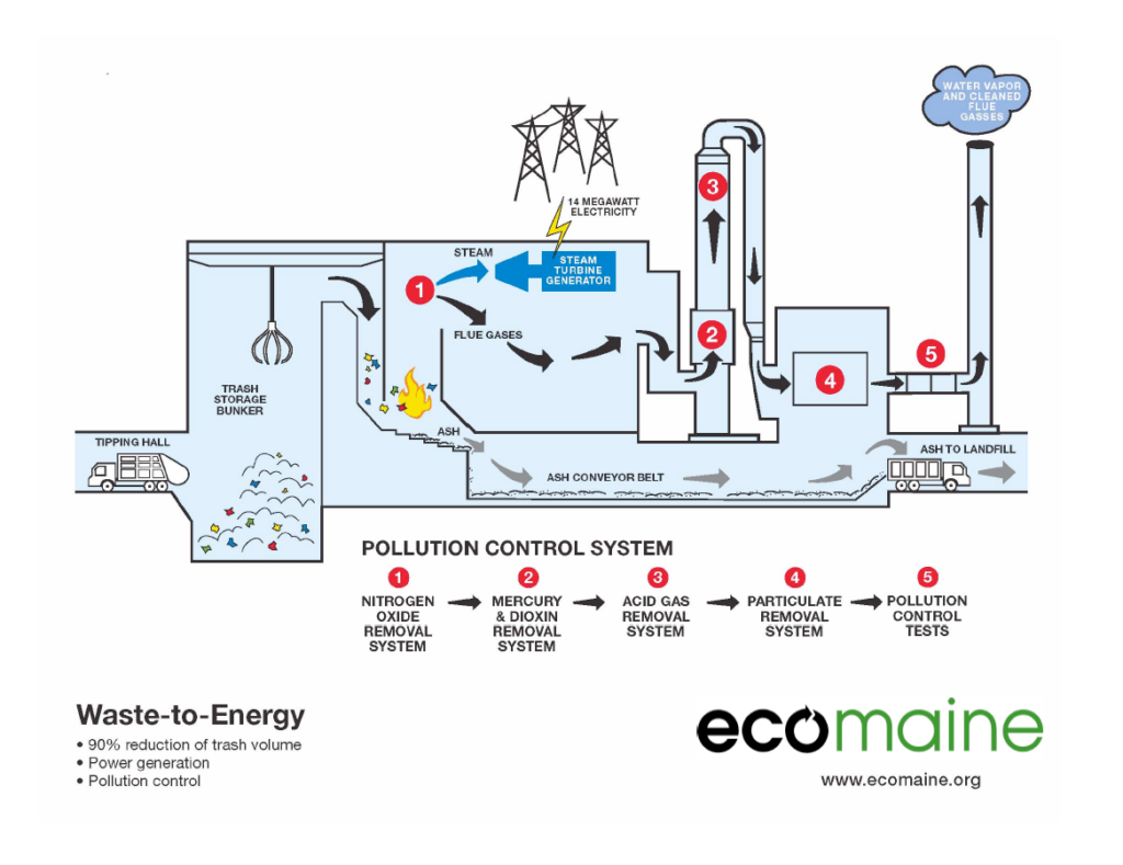
Every hafner waste to energy plant has controllers whereby a number of parameters are constantly analyzed. Combustion process energy recovery plant flue gas treatment plant ash handling ash processing. A typical scheme for an incineration plant operating on real waste and with energy recovery is given in fig. The various items of plant and equipment in the diagram are numbered and referred to in brackets below.
The following description should be read in conjunction with the typical process flow schematic diagram below.


